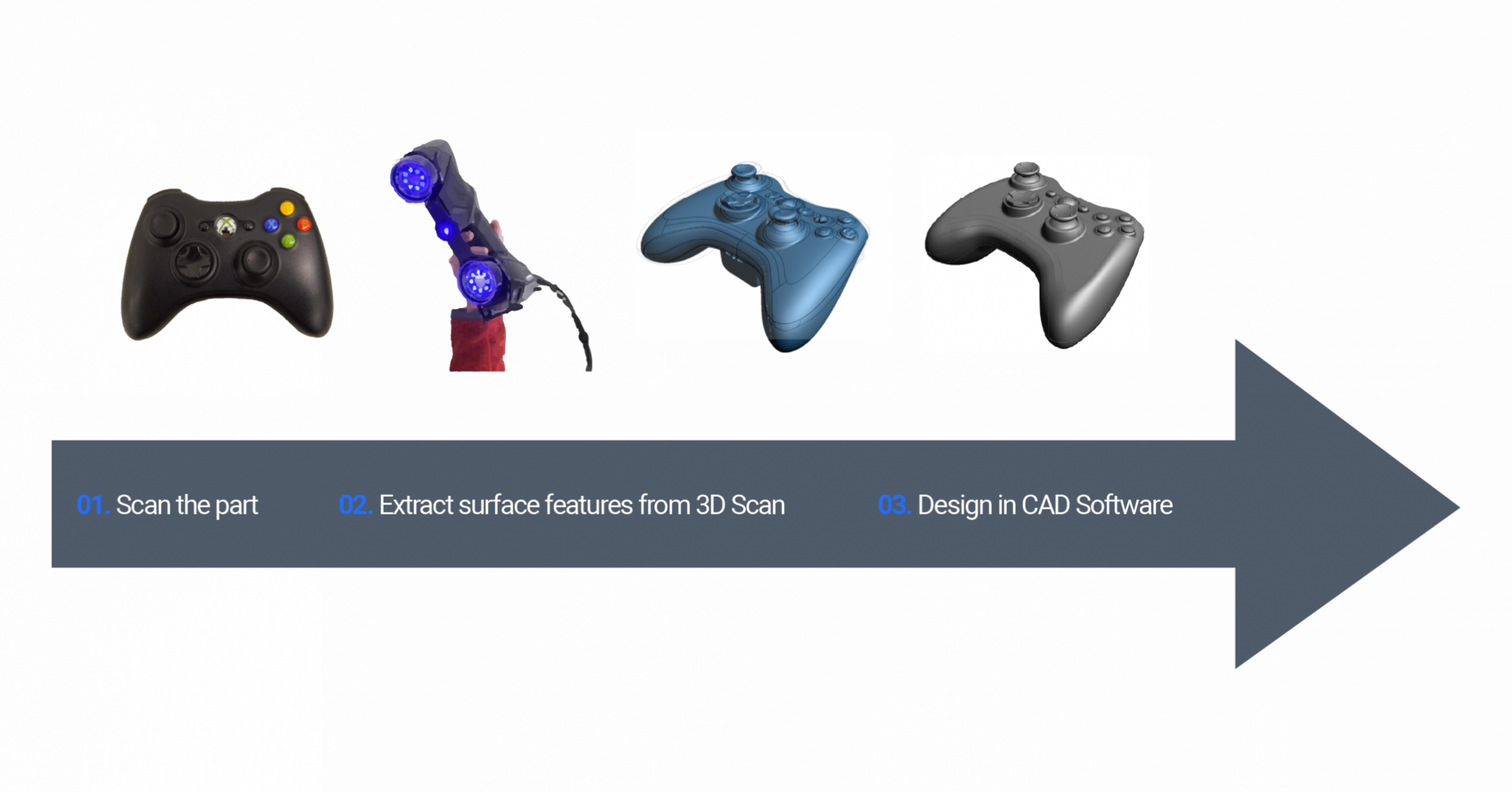
Reverse engineering is a common technique utilized in many fields, such as design, inspection and conception. Reverse engineering, in general, is the understanding and measuring of an existing object or assembly to enhance and improve it. Combined with the power of 3D scan technologies, reverse engineering allows to create a workable and useful 3D model compatible with all the standard 3D CAD modeling software such as Solidworks. 3D scanning is the quickest and most accurate technique to 3D model when facing complex geometry.
Uses of 3D reverse engineering:
- Design for Original Equipment Manufacturer (OEM);
Example : fixture bracket, casing or cover, adaptor etc. - Original design and Redesign existing part without any manufacturing defect;
- Creation of new component on existing product;
- Retrofit or adjustment of an existing discontinued product for example;
- Create a nominal reference CAD surface for Scan to CAD inspection;
- 2D layout;
- BIM or quick rendering of 3D long range scan point cloud;
- Finite element analysis (FEA).

Note that the Xbox is not property of Nucleom and has solely been used for educational purposes.
Design Intent
For the final CAD file to fit industry standard, design and conception assumptions are conducted from 3D scans.
- The deliverable will not always follow the 3D scan but rather makes sense of the purpose of the design;
Ex: 90° faces, perpendicular with the floor, pipe or any conduct straight, surface created without any anomalies present on the scan - Allows for cleaner and easier to read 2D drawings;
- Most common method for 3D reverse engineering.
As-Built/As-is
Where the reverse engineering respects the 3D scan surface as much as possible.
- The idea is to make the CAD model as close as possible to the 3D scan mesh;
Ex: if a wall or side of an object is tilted when assume to be 90°, conception will be made to respect the measured tilt, or if a pipe or conduct is in egg shape instead of being cylindrical, the 3D reverse engineering will take that in consideration - The 2D drawings will show “defects” but the deliverable will be closer to the reality;
- Used for external dimension analysis;
Retrofit an existing part into a newer CAD assembly when that said part has no CAD file available - Used for any position, location and deviation analysis;
- The most common method for this type of “as-built” reverse engineering is called the auto-surface;
- Should be considered when the exact location or dimension of the actual part is important, this way the 3D scan is respected.


